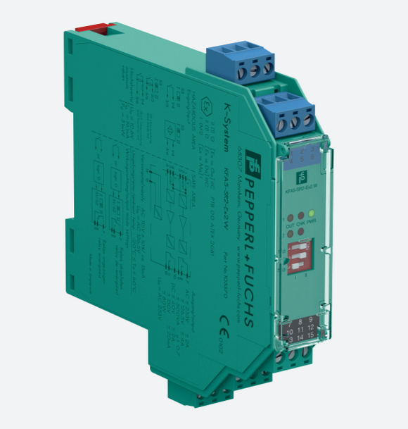

Zener Barrier Z787
- 2-channel
- DC version, positive polarity
- Working voltage 26.5 V at 10 µA
- Series resistance max. 327 Ω
- Fuse rating 50 mA
- DIN rail mountable
- With diode return
The Zener Barrier prevents the transfer of unacceptably high energy from the safe area into the hazardous area.
The zener diodes in the Zener Barrier are connected in the reverse direction. The breakdown voltage of the diodes is not exceeded in normal operation. If this voltage is exceeded, due to a fault in the safe area, the diodes start to conduct, causing the fuse to blow. The Zener Barrier has a positive polarity, i. e. the anodes of the zener diodes are grounded.
The Zener Barrier is for evaluation of signals from the hazardous area. The diodes of diode return prevent a current into the hazardous area, therefore the current assumption for intrinsic safety calculations is zero.
Depending on the application, increased or decreased intrinsic safety parameters apply for serial or parallel connection. For the detailed parameters refer to the Zener Barrier certificate. Application examples can be found in the system description of the Zener Barriers.
| General specifications | ||
|---|---|---|
| Type | DC version, positive polarity | |
| Electrical specifications | ||
| Nominal resistance | 300 Ω | |
| Series resistance | terminals 1, 8: max. 327 Ω | |
| Voltage drop | terminals 4, 5: 1.2 V + (36 Ω x signal current) | |
| Fuse rating | 50 mA | |
| Hazardous area connection | ||
| Connection | terminals 1, 2; 3, 4 | |
| Safe area connection | ||
| Connection | terminals 5, 6; 7, 8 | |
| Working voltage | ||
| Supply loop | max. 27 V | |
| Measurement loop | max. 26.5 V at 10 µA | |
| Conformity | ||
| Degree of protection | IEC 60529 | |
| Ambient conditions | ||
| Ambient temperature | -20 ... 60 °C (-4 ... 140 °F) | |
| Storage temperature | -25 ... 70 °C (-13 ... 158 °F) | |
| Relative humidity | max. 75 % , without condensation | |
| Mechanical specifications | ||
| Degree of protection | IP20 | |
| Connection | screw terminals | |
| Core cross-section | max. 2 x 2.5 ... mm2 | |
| Mass | approx. 150 g | |
| Dimensions | 12.5 x 115 x 110 mm (0.5 x 4.5 x 4.3 inch) | |
| Construction type | modular terminal housing , see system description | |
| Mounting | on 35 mm DIN mounting rail acc. to EN 60715:2001 | |
| Data for application in connection with hazardous areas | ||
| EU-type examination certificate | BAS 01 ATEX 7005 | |
| Marking |
|
|
| Voltage | 28 V | |
| Current | 93 mA | |
| Power | 650 mW | |
| Supply | ||
| Maximum safe voltage | 250 V | |
| Series resistance | min. 301 Ω | |
| Certificate | TÜV 99 ATEX 1484 X | |
| Marking |
|
|
| Directive conformity | ||
| Directive 2014/34/EU | EN 60079-0:2012+A11:2013 , EN 60079-11:2012 , EN 60079-15:2010 | |
| International approvals | ||
| FM approval | ||
| Control drawing | 116-0118 | |
| UL approval | ||
| Control drawing | 116-0139 (cULus) | |
| IECEx approval | IECEx BAS 09.0142 IECEx BAS 17.0091X |
|
| IECEx marking | [Ex ia Ga] IIC , [Ex ia Da] IIIC , [Ex ia Ma] I Ex ec IIC T4 Gc |
|
| General information | ||
| Supplementary information | Observe the certificates, declarations of conformity, instruction manuals, and manuals where applicable. For information see - www.control-automation.com/ | |