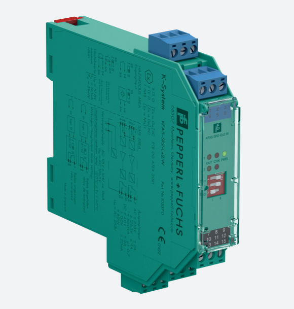


KFD2-STC4-Ex1, SMART Transmitter Power Supply
[ Ships within 1 day ]
SMART Transmitter Power Supply, KFD2-STC4-Ex1
- 1-channel isolated barrier
- 24 V DC supply (Power Rail)
- Input 2-wire and 3-wire SMART transmitters and 2-wire SMART current sources
- Output 0/4 mA ... 20 mA
- Terminals with test points
- Up to SIL 2 acc. to IEC/EN 61508
This isolated barrier is used for intrinsic safety applications.
The device supplies 2-wire and 3-wire SMART transmitters in a hazardous area, and can also be used with 2-wire SMART current sources.
It transfers the analog input signal to the safe area as an isolated current value.
Digital signals may be superimposed on the input signal in the hazardous or safe area and are transferred bi-directionally.
If the HART communication resistance in the loop is too low, the internal resistance of 250 Ω between terminals 8 and 9 can be used.
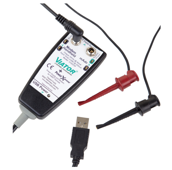
Test sockets for the connection of HART communicators are integrated into the terminals of the device.
| Product Description | |
|---|---|
| Input 0/4 mA ... 20 mA | |
| Output 0/4 mA ... 20 mA | |
| General specifications | |
| Signal type | Analog input |
| Functional safety related parameters | |
| Safety Integrity Level (SIL) | SIL 2 |
| Supply | |
| Connection | Power Rail or terminals 14+, 15- |
| Rated voltage | 20 ... 35 V DC |
| Ripple | within the supply tolerance |
| Power dissipation | 1.4 W |
| Power consumption | 1.8 W |
| Input | |
| Connection side | field side |
| Connection | terminals 1+, 2-, 3 or 5-, 6+ |
| Input signal | 0/4 ... 20 mA |
| Voltage drop | ≤ 2.4 V at 20 mA (terminals 5, 6) |
| Input resistance | ≤ 64 Ω terminals 2-, 3 ; ≤ 500 Ω terminals 1+, 3 (250 Ω load) |
| Available voltage | ≥ 16 V at 20 mA, terminals 1+, 3 |
| Output | |
| Connection side | control side |
| Connection | terminals 7-, 8+, 9 |
| Load | 0 ... 800 Ω at 20 mA |
| Output signal | 0/4 ... 20 mA (overload > 25 mA) |
| Ripple | max. 50 µA rms |
| Transfer characteristics | |
| Deviation | at 20 °C (68 °F), 0/4 ... 20 mA |
| ≤ 10 µA incl. calibration, linearity, hysteresis, loads and fluctuations of supply voltage | |
| Influence of ambient temperature | 0.25 µA/K |
| Frequency range | field side into the control side: bandwidth with 0.5 Vpp signal 0 ... 7.5 kHz (-3 dB) safe area to hazardous area: bandwidth with 0.5 Vpp signal 0.3 ... 7.5 kHz (-3 dB) |
| Settling time | 200 µs |
| Rise time/fall time | 20 µs |
| Galvanic isolation | |
| Output/power supply | functional insulation, rated insulation voltage 50 V AC |
| Output/Output | functional insulation, rated insulation voltage 50 V AC |
| Indicators/settings | |
| Display elements | LED |
| Labeling | space for labeling at the front |
| Directive conformity | |
| Electromagnetic compatibility | |
| Directive 2014/30/EU | EN 61326-1:2013 (industrial locations) |
| Conformity | |
| Electromagnetic compatibility | NE 21:2011 |
| Degree of protection | IEC 60529:2001 |
| Protection against electrical shock | UL 61010-1:2012 |
| Ambient conditions | |
| Ambient temperature | -20 ... 60 °C (-4 ... 140 °F) |
| Mechanical specifications | |
| Degree of protection | IP20 |
| Connection | screw terminals |
| Mass | approx. 200 g |
| Dimensions | 20 x 124 x 115 mm (0.8 x 4.9 x 4.5 inch) , housing type B2 |
| Mounting | on 35 mm DIN mounting rail acc. to EN 60715:2001 |
| Data for application in connection with hazardous areas | |
| EU-type examination certificate | BAS 99 ATEX 7025 X |
| Marking |
|
| Input | [Ex ia Ga] IIC, [Ex ia Da] IIIC, [Ex ia Ma] I |
| Supply | |
| Maximum safe voltage | 250 V (Attention! The rated voltage can be lower.) |
| Equipment | terminals 1+, 3- |
| Voltage Uo | 25.4 V |
| Current Io | 86.8 mA |
| Power Po | 551 mW |
| Equipment | terminals 2-, 3 |
| Current Io/Current Ii | 74 mA / 115 mA |
| Current Ii | 115 mA |
| Voltage Uo | 3.5 V |
| Current Io | 74 mA |
| Power Po | 64 mW |
| Equipment | terminals 1+, 2 / 3- |
| Voltage Ui | 30 V |
| Current Ii | 115 mA |
| Voltage Uo | 25.4 V |
| Current Io | 115 mA |
| Power Po | 584 mW |
| Equipment | terminals 5-, 6+ |
| Voltage Ui | 30 V |
| Current Ii | 115 mA |
| Voltage Uo | 8.7 V |
| Current Io | 0 mA |
| Output | |
| Maximum safe voltage | 250 V (Attention! The rated voltage can be lower.) |
| Certificate | TÜV 99 ATEX 1499 X |
| Marking |
|
| Galvanic isolation | |
| Input/Output | safe electrical isolation acc. to IEC/EN 60079-11, voltage peak value 375 V |
| Input/power supply | safe electrical isolation acc. to IEC/EN 60079-11, voltage peak value 375 V |
| Directive conformity | |
| Directive 2014/34/EU | EN 60079-0:2012+A11:2013 , EN 60079-11:2012 , EN 60079-15:2010 |
| International approvals | |
| UL approval | |
| Control drawing | 116-0428 (cULus) |
| IECEx approval | IECEx BAS 04.0015X |
| IECEx CML 15.0055X | |
| Approved for | [Ex ia Ga] IIC, [Ex ia Da] IIIC, [Ex ia Ma] I |
| Ex nA IIC T4 Gc | |
| General information | |
| Supplementary information | Observe the certificates, declarations of conformity, instruction manuals, and manuals where applicable. For information see - www.control-automation.com/ |
| Accessories | |
| Optional accessories | - power feed module KFD2-EB2(.R4A.B)(.SP) |
| - universal power rail UPR-03(-M)(-S) | |
| - profile rail K-DUCT-BU(-UPR-03) | |